

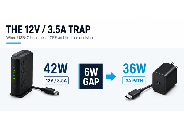
A CPE designed around 12V/3.5A requires 42W. At 12V, a 3A USB-C cable path is limited to 36W. That memorable 6W gap captures the wider issue: this is not just a PSU or connector change. For some products, the 2028 transition becomes a CPE architecture decision.
Products entering design now will continue to be deployed on the EU market after 14 December 2028. From that date, Commission Regulation (EU) 2025/2052 will apply to external power supplies placed on that market. Unless an exemption applies, AC-to-DC EPS will have to meet new interoperability requirements, including making the maximum power of a single output available through a USB Type-C or USB-PD port.
The 6W problem
The challenge is clear in three numbers:
- Existing CPE requirement: 12V × 3.5A = 42W
- Standard 3A path at 12V: 12V × 3A = 36W
- Resulting shortfall: 6W
For this 42W Standard Power Range example, the relevant fixed USB-PD voltage levels are 5V, 9V, 15V and 20V. 12V is not a standard fixed USB-PD level, although it can be delivered through a suitable programmable USB-PD implementation.
That means an existing 12V/3.5A product may not be made ready by simply replacing its barrel connector with USB-C. The EPS, cable, PD negotiation and CPE input architecture have to work as one compatible system.
15V as a practical migration route
For many 42W CPE designs, moving the product input to 15V may provide a practical migration route:
42W ÷ 15V = 2.8A
At 15V, the same 42W can be delivered below 3A, and 15V is a standard fixed USB-PD level. The lower current can also reduce cable losses and voltage drop, creating more operating margin across a detachable cable.
15V is not a universal answer. It may require changes to the CPE input stage and component ratings, followed by thermal, EMC, protection and interoperability validation. The right voltage depends on the complete design.
Can 12V/3.5A be retained?
Potentially. USB-PD does not prohibit 12V/3.5A. A suitable programmable implementation may support it when the EPS, CPE and a suitably rated, 5A-capable electronically marked cable are designed and qualified together.
The trade-off is greater dependency. A standard 3A cable or incompatible third-party charger could leave the device underpowered or unstable at peak load. For high-volume, always-on CPE, technical possibility is not the same as deployment robustness.
A CPE architecture decision, not just a PSU decision
Affected platforms now need a defined roadmap strategy. Depending on the product and any applicable exemptions, this may mean:
- migrating the input to 15V or another suitable standard PD voltage;
- engineering and fully qualifying a higher-current programmable solution; or
- retiring the affected EU-market model before the new requirements apply
The Regulation does not invalidate CPE already deployed in the field. Under specified conditions, certain replacement EPS for legacy products may also continue to be placed on the market until 14 December 2033. That provision is not a general extension for new product platforms.
Because products designed now may remain on the EU market after 14 December 2028, OEMs and operators should identify current and planned CPE using 12V above 3A, confirm the EPS regulatory position and decide the future architecture during current roadmap planning, before hardware is locked.
Waiting risks late board changes, repeated validation, delayed launches, fragmented regional SKUs and obsolete inventory. Acting now creates time to design, test and qualify the complete power system properly.
Start the transition with NetBit
USB-C PD is not about finding any charger with enough watts. It requires a stable, compatible power system for equipment connected around the clock.
NetBit helps CPE manufacturers and network operators identify at-risk legacy specifications and develop CPE-grade USB-C PD solutions for the 2028 transition.
If your roadmap includes a 12V/3.5A or any 12V design above 3A, now is the time to review it. Contact sales@netbit.com to discuss the most practical route to a compliant and reliable next-generation CPE power architecture.